Spare-Part Surgery
Back To OverviewStress (\(\sigma\)) is measured in Pascals.
\(\sigma =\frac{F}{A}\)
Where \(F\) is force and \(A\) is cross-sectional area.
Strain (\(\mathcal{E}\)) has no units.
\(\mathcal{E}=\frac{\Delta x}{x}\)
Where \(\Delta x\) is the extension and \(x\) is the original length.
Young's modulus (\(E\)) is measured in Pascals.
\(E=\frac{\sigma}{\mathcal{E}}=\frac{Fx}{A\Delta x}\)
The limit of proportionality is the point at which the graph stops being linear.
The elastic limit is the point where the material stops deforming elastically.
The yield point is the point where strain increases with no additional stress.
The breaking stress of a material is the maximum stress before the material breaks.
The gradient of a stress-strain graph is equal to the Young's modulus of the material.
The area under a stress-strain graph is equal to the work done per unit volume in deforming the material.
CORE PRACTICAL 5: Determine the Young's modulus of a material.
Diagram:
Method:
- Set up equipment as shown in the diagram.
- Measure the diameter of the wire using a micrometer, taking measurements at multiple angles & points along the wire, and finding an average.
- Add masses to the end of the wire in equal steps, recording the distance of the marker each time.
Analysis:
- Calculate the cross-sectional area of the wire using the equation \(A=\pi r^{2}\).
- Calculate the extension of the wire for each mass, which is \(\ position\ of\ marker-original\ length\).
- Calculate the force applied for each mass using the equation \(W=mg\).
- Calculate the stress and strain for each value of \(F\) and \(\Delta x\) using the equations \(\sigma =\frac{F}{A}\) and \(\mathcal{E}=\frac{\Delta x}{x}\).
- Plot a graph of stress against strain, and then calculate the gradient to find Young's modulus (since \(\sigma =E\mathcal{E}\)).
Safety:
- Wear goggles whilst doing the experiment, incase the wire snaps.
- Place something under the masses to catch them if the wire snaps, and avoid standing under them.
Errors:
- Use a longer wire in order to reduce percentage uncertainty.
- Use a thick enough wire, to ensure that you can measure a wide range of values before the wire breaks.
The area under a force-extension graph gives the elastic energy stored in the material.
For a Hookean material, you can also find the elastic energy using the equation \(\frac{1}{2}F\Delta x\).
The focal point of a converging lens is the point where incoming rays of parallel light meet.
For a diverging lens, the focal point is the point where incoming rays of parallel light appear to be coming from.
The focal length is the distance from the lens to the focal point. A diverging lens has a negative focal length.
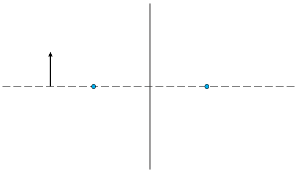
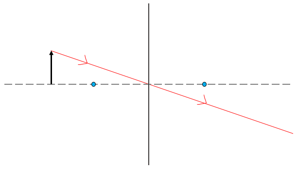
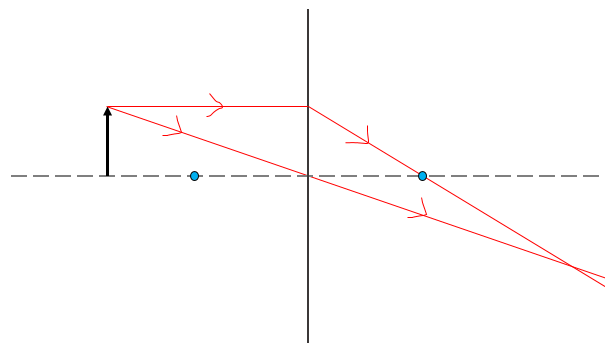
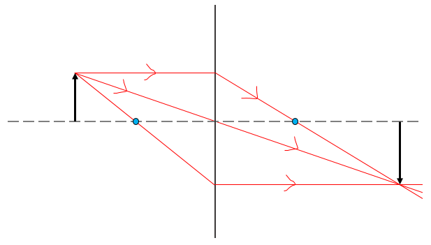
To draw a ray diagram:
- Draw the axis, focal points, lens and object.
- Draw a ray from the top of the object, through the centre of the lens.
- Draw a ray parallel to the axis through the lens, and then from the lens through the focal point.
- Draw a ray from the top of the object through the focal point to the lens, and then parallel to the axis.
The power (\(P\)) of a lens is measured in Dioptres, or \(m^{-1}\).
\(P=\frac{1}{f}\)
Where \(f\) is the focal length of the lens.
To combine the power of multiple lenses:
\(P=P_{1}+P_{2}+P_{3}+\ldots\)
A real image is an image that can be projected onto a screen, and is indicated by a positive image distance.
On the other hand, a virtual image cannot be projected onto a screen, and is indicated by a negative image distance.
The thin lens equation states that:
\(\frac{1}{f}=\frac{1}{u}+\frac{1}{v}\)
Where \(f\) is the focal length, \(u\) is the object distance, and \(v\) is the image distance.
Magnification (\(m\)) has no units.
\(m=\frac{image\ height}{object\ height}=\frac{v}{u}\)
Where \(u\) is the object distance and \(v\) is the image distance.
At a boundary between different media, a wave can be reflected and transmitted. The larger the difference in the densities of the media, the more of the wave is reflected.